Alle berichten van Hans Nouwens

Theater in the attic

Trains, cars, streets, backgrounds, houses, lights, sounds … We do our best to model our little slice of the Real World as realistically as possible, presenting a complete slice of miniature life. However, what happens when nighttime descends? CLICK! Someone hits the light switch, and it’s night…. not exactly prototypical.

Visitors to Railz Miniworld in Rotterdam (the Netherlands) or any professional layout have seen a far better solution in action. As dusk descends on the layout, the sounds begin to change, the horizon turns red, and lanterns and house lights go on one by one. Even miniature fluorescent streetlights turn on one by one in sequence. It is a slow and smooth transition from day to night. The visitor experiences a more prototypical 24 hour day, in 24 minutes.

As designer of the Railz Miniworld installation, I received many requests for information for an installation for a “typical” small model railway room. The challenge in answering these requests is to scale the Railz Miniworld examples and solutions down to a level which is both technically and financially within the reach of the average modeler or club.

Download theTheater_in_the_attic_v1.0_ENG, or download theTheater_op_zolder_v1.0 here.

[[please be aware that the described concepts are from 2011. Today one should re-evaluate the choices made in the document]]

I’m curious about your reactions, please  let me know  what you think!

tweede MCC workshop was een succes!

Besproken onderwerpen zijn o.a.:

  • SMD solderen
  • het ontwerpen van wegen
  • het plannen van de signaaldraden
  • Het programmeren van de MCC decoder
  • Demonstratie OC32 mogelijkheden.
Naast de theorie hebben we uiteraard niet stilgezeten, samen hebben we zitten werken aan het aansolderen van de LED’s en het monteren in de vrachtwagentjes. Tussen de twee dagen is er door de cusisten thuis gewerkt. Op de tweede cursusdag waren er meerdere werkende modellen. Een bijzondere prestatie. In het bijzonder de schaal-N auto die tot onze grote verassing achteruit bleek te rijden! Het laatste nieuws is dat de draadjes nu omgedraaid zijn en dat ook deze klaar is.
Mocht je zin hebben om ook eens twee dagen  met ons samen aan de slag te gaan, laat dat dan even weten.

MCC Workshop (inschrijving vol)

Naast Leon zal ik zelf ook de twee dagen aanwezig zijn om de workshop te begeleiden.

Status 17 december: 8 inschrijvingen = VOL !!!

Heb je desalniettemin belangstelling, laat het toch even weten. Mocht er iemand afvallen, dan kunnen we je wellicht nog blij maken en mensen die zich nu aanmelden hebben voorrang als er na deze workshop een vervolg komt.

Programma

Dag 1:

  • Theorie: Principes en opbouw van Dinamo/MCC
  • Praktijkoefening SMD-solderen
  • Theorie: Ombouw Faller auto
  • Praktijk: Ombouw van je eigen auto

Huiswerk:

  • Het afmaken van je eigen auto, indien deze nog niet klaar is.

Dag 2:

  • Praktijk: Het testen en configureren van je auto
  • Theorie: Wegenbouw
  • Praktijkoefening: Het aanleggen van een (stukje) weg
  • Theorie: inrichten Koploper voor Dinamo/MCC
  • Praktijk: Het maken van een Koploper database voor de testbaan
  • Gezamenlijke meesterproef: 6 auto’s op de testbaan (of op de wegen van Railz Miniworld!)

Randvoorwaarden

  • Voldoende motorische vaardigheid om een draad door het oogje van een naald te steken
  • Enige normale soldeervaardigheid. Het is prettig als je thuis zelf beschikt over een goede soldeerbout of een eenvoudig soldeerstation.
  • Basiskennis Koploper (je hebt minimaal Koploper een keer gedownload en geinstalleerd en geprobeerd een eenvoudige database op te zetten)

Data

Dag 1: Zaterdag 23 januari 2010 (9:30 – 17:00)
Dag 2: Zaterdag 30 januari 2010 (9:30 – 17:00)

Lokatie

Railz Miniworld (Weena 745, Rotterdam)

Connecting MCC detection

Ok, the documentation is there. It’s available in English too. I still get questions about connecting the reed switches. The diode matrix I made for my test track was a quick hack with available materials. After evaluation this design was not very suited for a publication. This is a second attempt to design a cheaper alternative for connecting the reed switches.

About the UCCI. The black multi pin connectors you may recognize as a floppy or hard disk cable connector are used on the UCCI to connect the reed switches. You cannot connect the switches directly to the controler. They are multiplexed. Now for some of us this is a somewhat mysterious technique. I will not try to explain this, just google for the numerous explanations. Just think of it as a way to connect lots of reed switches with as little cables as possible.

ucci2_large


Leon kindly designed a diode matrix for us. You can order it from his website.  Before this was available I designed a prototype for Railz Miniworld. Combined with the test track thingy I now present a do-it-yourself version of the SWDEC.

swdec_small

With two flat cables you can connect 128 reed switches. It does not matter which connector you use first. The flat cables can me about 10 meters each.

It is advised to use them as described in the next picture:

16-26pin connector


All the connectors are female connectors.

16pins-female


The reed switches and diodes must be connected as shown in the next picture. Each reed switch is connected to a single Sxx channel. the return connection is one of the SDx channels.

For every connector you will have to choose a different SD channel.


connecting reed and diodes

The board to use is called strip board or Veroboard.

stripboard


First the back side. In the middle you will have to remove three stripes of copper. On the corners you will need some holes. Remove the copper around the hole to prevent a short circuit here.

The grey line is a extra connection you will have to solder on the copper. It connects the 8 bottom stripes.

selfmade flat cable matrix

On the front side you place the connector. This is a print header. Buy these in long strips and break or cut off 16 pins.

header
Eight diodes of the type 1N414B. These are the cheapest you can find. The indicator ring is on the outside pointing away from the middle 16 pin connector.

The green connectors are very expensive.

R101538-01

Of course you can decide to skip these and solder your wires directly to the copper on the back.

The green connection is unique for every matrix you make. It chooses the return channel. In the example SD2 is chosen. If you look at the back you can see that this connection touches the wire on the back side indicated with grey in the first picture.

The reed switches are connected as shown. One leg on the SDx channel, the other via the diode to the Sxx channels.

connecting matrix

That’s it. Don’t forget to change the green connection for every board you make. On every flat cable you can connect 8 of these boards.

Good luck!

Please send me some pictures of your results.

Hans.

Testbaan – detectie

De auto’s kunnen nu hun rondjes maken maar kunnen nog niet aangestuurd worden. Onder de baan moeten de volgende zaken gemonteerd en aangesloten worden:

  • een reed-contact per blok
  • diodematrix
  • de UCCI
  • Een OM32

De UCCI heeft wat ruimte nodig. De vermogensweerstanden en de driver er voor (met de zwarte koelribben) geven behoorlijk wat warmte af. Leon raad aan een afstand van 1 cm aan te houden. De OM32 kan direct op de plank.

De voeding haal ik uit een adaptor. De groene stekker gebruik ik om deze voeding door te voeren naar de OM32. Op deze testbaan zal ik niet veel vermogen verbruiken. Kijk in de UCCI handleiding voor de aanbevelingen.

De blauwe draden zijn de zenddraden die langs de wegen liggen. Een enkel paar in mijn geval.

Via een lintkabel sluit ik de reed-contacten aan. Ik had niet de juiste stekkers in huis dus ik probeer het af te maken met de (gratis) dingen die ik nog had liggen. De lintkabel is een kabel die in een PC wordt gebruikt voor een floppy drive. Daar heb ik er nog wel een paar van op de zolder.

Na de diodematrix gebruik ik weer zo’n kabel, het blijkt een lekker overzichtelijke methode te zijn. Niet te veel losse draden. Aan de uiteinden zitten de reed-contacten.

Op de OM32 zit een klein testprintje met een zestal leds. Dit is tijdelijk.

Een detailfoto van de ter plekke verzonnen diodematrix. Leon biedt een matrix aan met acht aansluitingen, ik had er minstens 24 nodig.

227_2709

Op ieder setje pennen kan je een reed aansluiten. via een diode komen ze om de beurt bij de SD kabels 0..3. De SD kabels 4..7 gebruik ik niet.
Die vier grote diodes hebben geen speciale betekenis. De kleintjes waren gewoon op.

Vooraf heb ik geen moeite gedaan om uit te rekenen welke nummers de detectors zouden krijgen. Het maakt in de software namelijk toch niets uit.
Bedenk wel dat de nummers die dinamo geeft door koploper met 1 opgehoogd worden.

227_2710


Hier liggen de reeds in de buurt van de gaten onder de geleide draad. Het rechthoekige gat heeft geen functie. Hier zat vroeger een handvat in, de plaat was vroeger een deurtje.

227_2711

Een reed aangesoldeerd.

227_2712

Met hete lijm

227_2713

En dan tegen de geleide draad aanplakken.

227_2714

Al snel zitten de schakelaars vast. Op deze manier is het een makkie. Bij Railz heeft een medewerker zo 500 contacten achteraf onder de tafel aangebracht op zijn rug. Op de testbaan was het in tien minuten gedaan.

227_2715

De lintkabels gaan ook met hete lijm vast aan de tafel. Ik heb nog een paar aansluitingen over.

227_2716

De hergebruikte stekkers hebben twee gaatjes te veel.

227_2717

Al met al een relatief snelle manier van aansluiten, minimale kosten en het werkt!

Hans.

Stadtwerke part 2

The second part of the building report of the Stadtwerke bus. In the previous part I described the lights, this time the mechanics.

The floor of a Rietze bus is prepared to make room for the battery holder. The chair stands are cut of with a knife. In the end some of the chairs will be but back including some passengers.

A nice fit. This is a double AAA holder. You will have to do some searching to find this at a reasonable price. I have seen prices up to € 4,50. This one costs € 0,35.

The holder does not hold very well with glue. I needed two extra strips to get some structural strength. I also sanded the bottom of the holder. It was not not completely flat.

Next was the steering mechanism. This is a difficult job. It takes a lot of time to rebuild a support structure. The extra room needed for the steering arm got me into trouble. The floor is not in two pieces. In the end I decided to glue the front to the cover, the back end is removable.

See the extra room you will need for the steering wheels.

It is very important to get the wheels exactly on the same place as they used to be with the static axle. This is why I leave the original support. Later I made some extra room to prevent friction.

Here you can see the charger plug and the micro switch.

Just checking if the gear and motor will not hit the ground.

Extra support on the front

batteries are connected to the charger plug and micro switch. First three are for charging. The connections are earth, plus, earth. It does not matter how you connect the charger, it cannot be polarised wrongly. The send three are from the switch. if in the left postition it connects the battery to the charger, in the right position it connects the battery to the decoder. There is no way to connect the charger to the decoder. Remember the Geest #3 truck?

A second precaution is to add a small fuse in between the red wire and the switch. This is not done in this bus.
If  you look for a fuse, remember that i should allow for charging too. In my case you will need at least a 1000 mA fuse.

The decoder will be in this same spot too. All the cables from the cover end up here too.

The result

Stadtwerke part 1

This time a report about a bus I build in commission for a MCC enthousiast. He wanted two buses, this is the first. I have writen about this one before. This is the bus with the very difficult motor from SolExpert.

The original chassis was a Rietze “MAN NL Stadtwerke Verkehr”. This is a static model. I had to make room for the motor, add batteries and a steering mechanism. Watch and learn!

First action is to take out the plastic covers and moke some more room for the LED’s. The covers are glued back in there original places before placing the LED’s behind them.

remember how smal the 0603 LED’s are? This is a orange one for the side of the bus. I had to make 10 of them.

The tail lights are combined with the indicator. This saves one wire. In the middle is the common kathode.

Same is done for the head lights and indicators. The “big” LED is a warm white 1206 LED. They are expensive but have a very nice colour.

This time I drilled a small hole in the side and glued the LED’s on the outside. This is not very hard to do. A disadvantage is that the LED’s are very vulnerable. On a other bus I glued them on the inside. Much nicer!

Ok, it’s getting messy already.

Tail lights fit nicely in the prepared cavity.

As do the head lights.

Wires of the side lights are glued to the inside. I tried to make a little channel to prevent them sticking out. This bus will have removable batteries on the inside, it will be disassembled a few times.

The white rubber underground is a rubber underlayment for a carpet. It is to prevent scratches on the bus (and the table). Just be carefull: don’t leave the bus on it too long (more than a week). The rubber damages the delicate paintwork eventually.

Some light for the passengers. Again the warm white LED’s. On the right side you see a collection of SMD resistors. I had to tweak them a few times to get the desired relative light levels.

The result

comparing motor and gears

After adding decoders to a ready to run Faller Car System Car the next challenge is to completely build a car yourself. The truck or car to fit your landscape is probably not in the Faller catalog anyway.
To do this you will need a steering mechanism, a motor and gears. I have tested some gears and want to share my opinion with you.

Faller Setra

First in line is a standard Faller car. This is a motor and worm gear from the Faller Setra bus. This is the luxury set which includes head and tail lights and has beautiful white (according to the picture) interior lights. About the lights I will write later.

The worm gear in this bus is an improvement. Older buses I have seen have a very delicate construction which tend to break after a few hours. This construction is much better.
The motor sounds like we are used to, it behaves reasonable. The bus runs at a blazing speed!

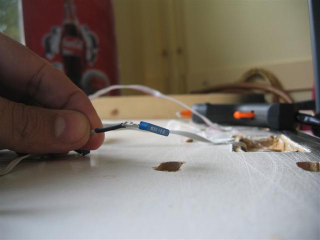
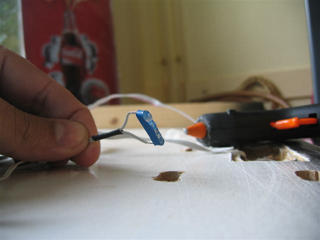
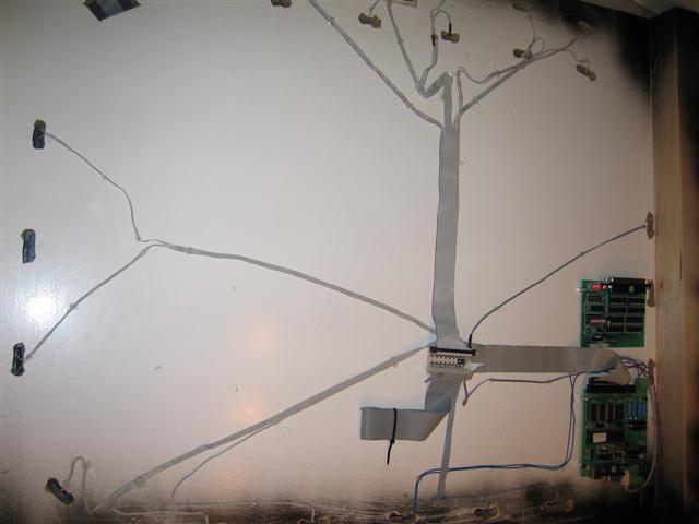
In the picture you will not see any cables, they are all removed in preparation of the dinamo MCC decoder.

Lemo-Solar

The first self-made trucks I made in 2007. In those days the only decent gears i could find were the Lemo-Solar gears.

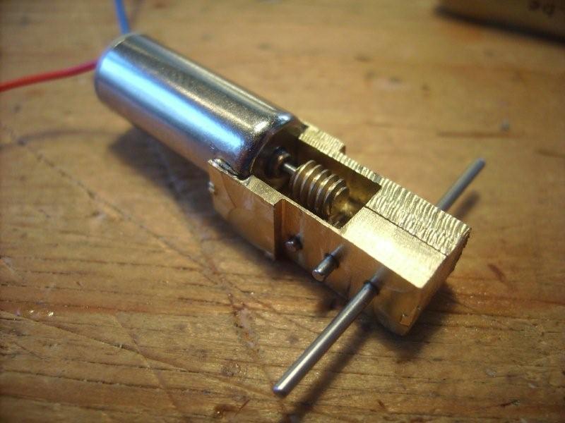
German details: Micro – Glockenankermotor mit Getriebe 15:1
Antrieb bestehend aus: Glockenankermotor 1016N003G, Winkelgetriebe 15:1 mit Schnecke und Schneckenrad ( Messing ), Doppelachse.
Als Antrieb faller Modelle M 1:87 oder Modellbauantrieb, Modelleisenbahnantrieb. Betriebsspannung 0,5 – 6 Volt, 18-280 mA, Masse: ( L x B x H ) 26 x 10 x 12 mm, Gewicht 10,7 Gramm, Abgangsdrehzahl 4,8 Volt = 1500 Upm, 3 Volt = 840 Upm, 1,5 Volt= 420 Upm.

11432b

This gear costs 46 euro excluding shipping (from Germany). This is a very expensive set. The motor is a real Faulhaber.  It delivers a great deal of torc and takes a lot of electric current. We had to ad extra condensators to keep the power supply stable. It was distorting the reception. Technically speaking a good motor.

After using it intensively, as we do at Railz Miniworld, we find that the combination of a brass worm gear is not so good. The wear is disastrous. This is a very expensive set for the amount of kilometers it can run.

 Microantriebe

This is a motor I found at the webshop from Mikroantriebe.  The ordering went not without trouble. The first shipment never made it to my house. Only after numerous emails and threatening to make a PayPal dispute the second package was sent.835_0

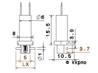
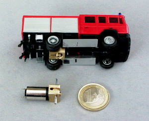
The motor of my choice was the “G20M660P Gearmotor with ratio20:1”. This one costs EUR 15,50. The cheapest motor I found ever. The English text on the website was very limited

If you switch to German you can find this:
“Getriebemotor mit 1 stufigem Schneckengetriebe. Gehause, Schnecke und Zahnrad aus hochwertigem POM gefertigt. Achse aus Stahl 24mm Dieser Motor kann z.B. mit unseren GWT Getrieben einfach zu 180:1 bis 400:1 Getrieben kombiniert werden oder z.B. direkt als z.B. Faller Car Antrieb eingesetzt werden”

The “POM” was not translated in English so to me it was a suprise to see that the gears are plastic, not metal. Of course POM is a very good plastic, not uncommon in gears. This could work. The picture (right) on the current website was not there in december 2008.RIMG0181

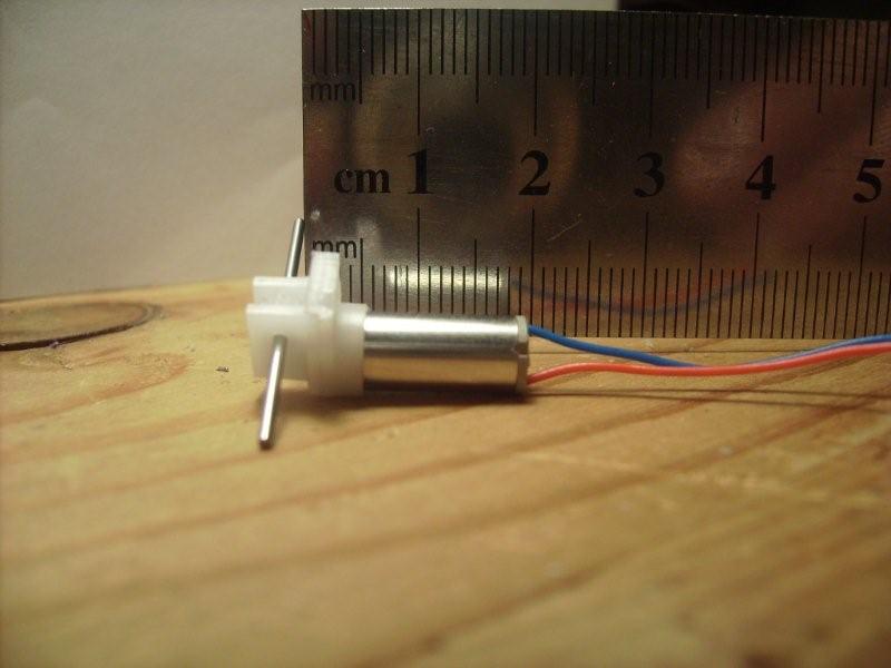
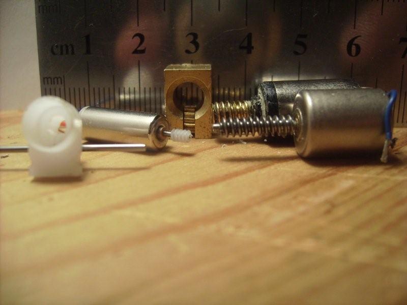
What catched my eye is the size of the little thing. Of course I had seen the dimensions on the website but never realized that it was this small.

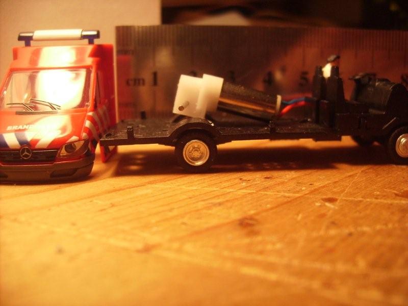
Look a the next picture where you can see the Faller motor, a Faulhaber and the little G20M660P.

This is to small for a H0 truck or bus. Maybe a n-scale bus of a small H0 car.

RIMG0185

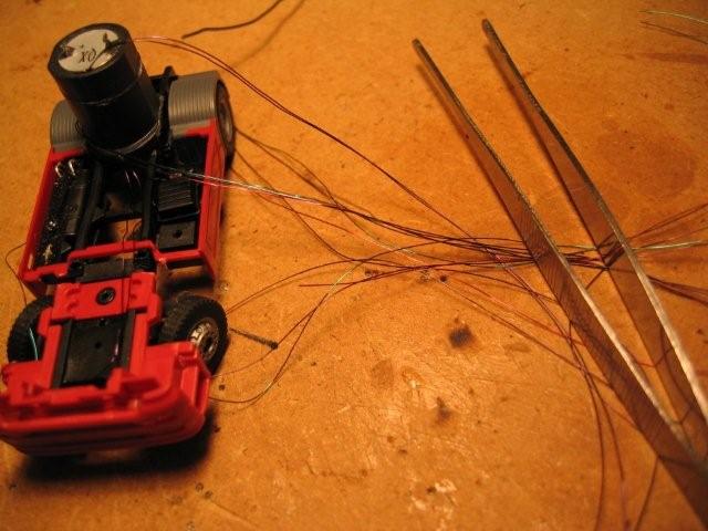
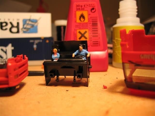
The gear compared to a family car.
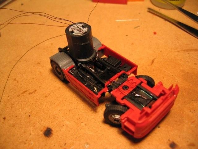
RIMG0188

Or my next project.

RIMG0186

Indeed, a fine match.

RIMG0192

Gear box kit G90 with motor M705

First alternative for the little G20M660P is this gear. The G90 with  M705 costs EUR 30,00 excluding shipping. Shipping from Germany to the Netherlands is 14 Euro!!!

To my suprise the gear is sold by Conrad too, EUR 29,99. If you pay with iDEAL shipping is free. It is the unfinished set, how hard can it be?

The set includes small holders to help with the construction, it also has very good instructions. No problem. The SolExpert advices to use the special  Loctide 648. A normal super glue will work fine I thought.

RIMG0199

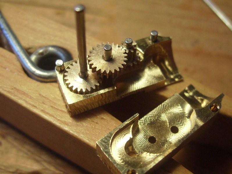
looks beautiful! real engineering, what can go wrong?

RIMG0198

And then reality hits in!

RIMG0201

After one (1) minute of action the main gear came loose. I had to completely remove the gear from the bus. Glued the gear again and put it back in the bus. This took two hours! Result: one minute of driving before it failed again.

The special glue is not available in any normal shop in my home town. The 14 euro shipping prevented my from ordering the glue in Germany. At ebay I found a small fake bottle of loctide for 5 pounds and 2 pounds shipping.  Within a week I was ready for a next attempt.  Got everything out of the bus, glued the gear to the axle and waited. Glued the gear and motor back into the bus and….The gear was holding but to my disappointment it was glued not exactly perpendicular to the axle. After 2 cm it was completely stuck! There we go again. This is starting to get irritating!

With a new and somewhat thicker axle i got the gear perpendicular on the axle. Build everything together only to find the next problem. The gears runs but not smoothly.

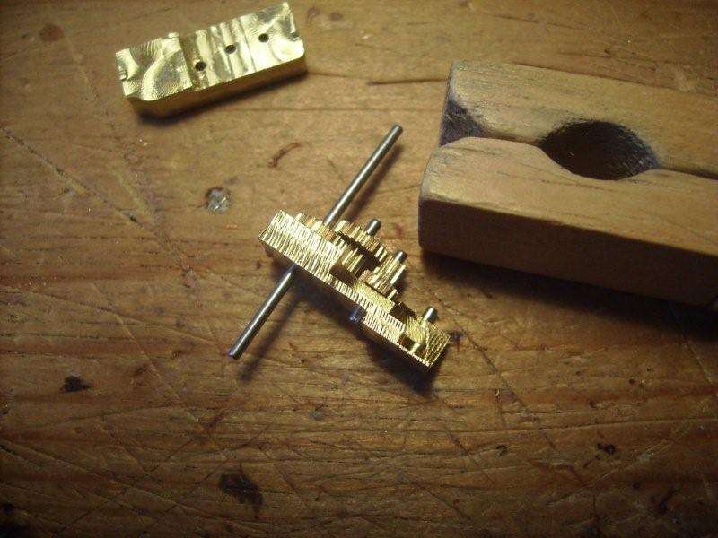
In my last attempt I completely removed all the gears, including the small ones, check every detail and found some tiny glue residue. After removing this and removing the very very small milling imperfections the gears were finally working.

Final result: lots of motor noise and a bus that runs to slow. The 1:90 gear ratio is too much.

This cost me a lot of money and time without a good result; please, if you buy this gear, buy it assembled form the German site.

MikroModellBau

The next alternative is a set of gears form MikroModellBau.

I ordered two models. The KG-1048 and the KG-1019-30-s. They cost EUR 31,50 and EUR 25,00. Shipping 3,50. A order is confirmed by a email including a paypal transaction. Perfectly on time.

The gears are already put together and work very smoothly. There are very clear instructions included. Especially how to shorten the axles without damaging the internal gear. Because of my previous experience I know how important this is!

RIMG0252

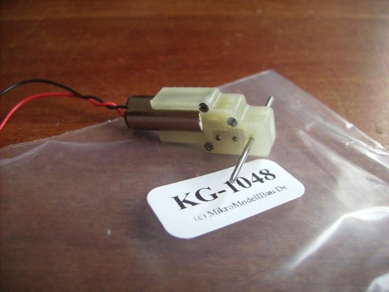
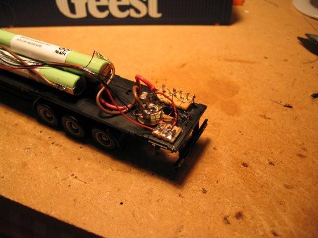
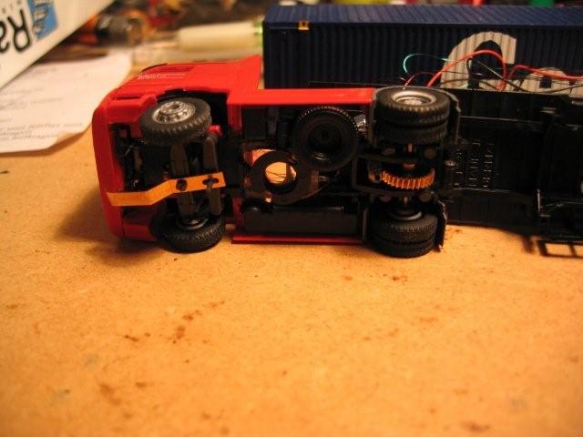
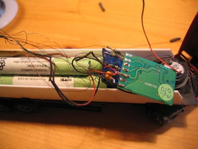
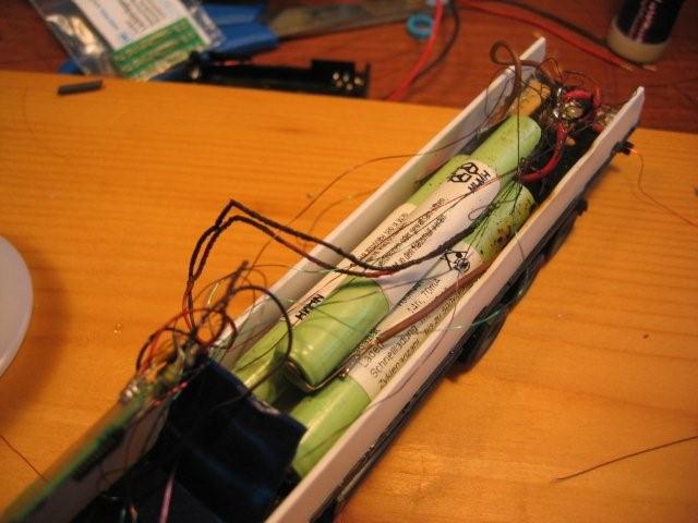
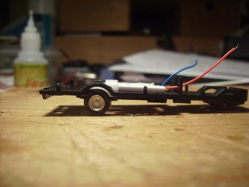
This second gear I tested in a bus. The flat top side is very good, the material glues very well.

RIMG0259

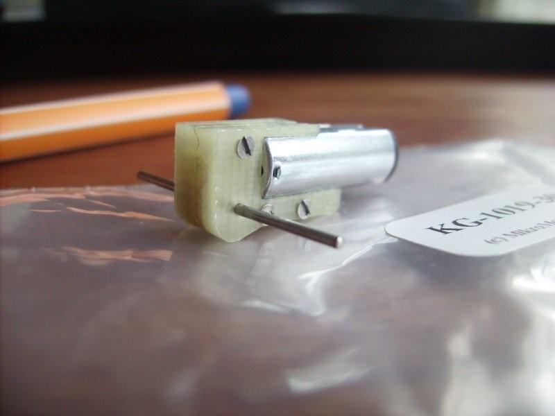
The speed is fine. The bus has somewhat smaller wheels and still it is a little fast. This will be fixed by adjusting the decoder. As you can see I decided to wait before shortening the axles.

RIMG0267

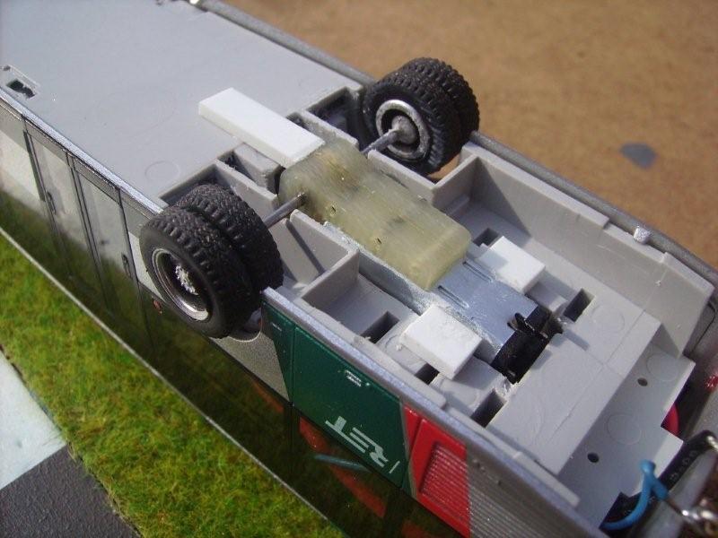
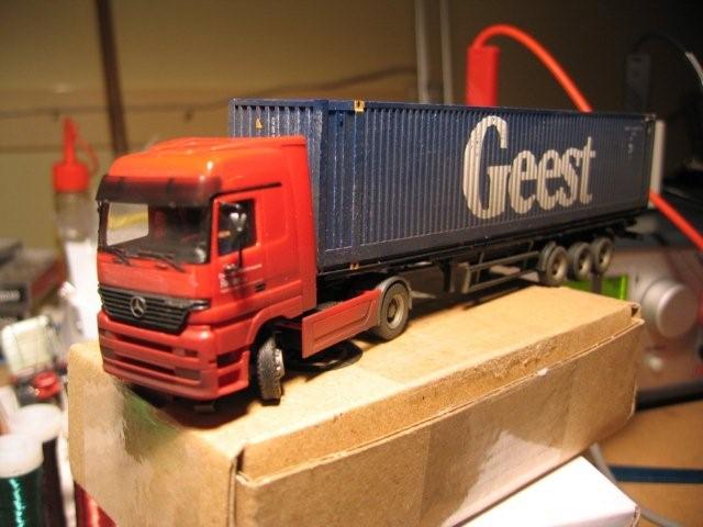
The first test run is a success. I’m finishing this one and make a 10 buses for Rails Miniword. We will see how long this gear will hold.

Conclusion

  • Faller gear and motor are fine, wear is horrible. Fine for at home but not suitable for Railz
  • Lemo-Solar. Very expensive, same wear.
  • MikroAntriebe G20M660P.Cheap but not enough power for H0 trucks.
  • SolExpert G90. Very hard to assemble yourself. Too slow!
  • MikroModellBau KG-1019-30-s. runs smoothly. First experience very positive.

Do you have experiences with these motors and gears, please let me know. If you want I can add your comments to this article.

Roadz Geest

#03, Geest. Een beroemde auto uit de allereerste serie. Deze auto heeft ongelovelijk veel gereden bij Railz Miniworld. Als er publiek was reed deze auto minstens 2 Kilometer per dag. Op de container na waren ondertussen alle onderdelen al vervangen. Na een binnenbrandje heb ik de resten aan elkaar gesoldeerd en de motor er uitgehaald. De auto staat nu ergens stil op de modelwereld met de lampjes te knipperen. Een rustige oude dag voor deze veteraan.

Let op: de gebruikte technieken zijn nu niet meer actueel. Deze eerste serie zijn echt prototypes geweest.

De lakdraad loopt vanaf de leds, langs de motor helemaal door naar de decoder. Verderop lees je waarom dat niet zo’n goed idee is.214_1443

214_1444

Aan het interieur en de chauffeur wordt ook gedacht.

214_1449

Zie hier de eerste generatie decoders. Het  zijn nu verzamelstukken geworden.

Zo’s zee van ruimte en dan toch de decoder op zijn kant! Dat wat om de decoder toch aan de voorkant te houden EN de accu’s zo ver mogelijk naar voren te houden om het gewicht op de aandrijfassen te krijgen.

De accu’s zijn 3x700mAh naamloos met soldeerlipjes. Nu gebruiken we twee cellen, dat is met decoder 2.0 voldoende.214_1455

Ook zo’n test: laden met een mini-jack plug. Groot nadeel: tijdens het aansluiten maakt de stekker even sluiting. Deze methode is nooit in productie geweest. Let op de briljante manier om even snel een kabelbindertje te maken, een klein lakdraadje getwist om een paar andere lakdraadjes.214_1456

Een eenvoudig spoeltje, niet zelf gemaakt. Het reed-contact liet ik nog zitten.214_1459

Een airbrush actie van Hein. Dit maakt het wel een stuk realistischer.214_1463

Herinner je nog dat briljante kabelbindertje? Dat heeft ook zo zijn bijeffecten. Lakdraadjes zijn erg fijn om aan een LED te solderen. Ze zijn echter erg gevoelig voor slijtage. Het constante bewegen en trillen heeft er toe geleid dat de isolatie versleten was zodat er kortsluiting kon onstaan.
Tijdens het laden zijn alle draden verbrand!224_2417

Vraag die nog openstaat: waarom is de oplader doorgegaan, we hebben zo’n slim apparaat. Had die niet kunnen zien dat de hoeveelheid stroom niet binnen de normale grenzen lag?

224_2418

Naast het kabelbindertje bleek later ook dat het niet zo verstandig is om de lakdraadjes langs de motor te laten lopen. Zeker niet omdat deze bij elke bocht langs elkaar schuiven!224_2419

224_2420

Dat hebben we dan ook maar weer geleerd zeggen we dan.