
People ask me about the dimensions of the roads. How close can the road halves be together? what about the corners?
In this article I’ll describe a practical way to construct a two-lane road and give some examples of how to construct a corner.
Basic dimensions
The minimum radius I use as a practical average is 200 mm (7.9 inches). The real minimum is about 150 mm (5.9 inches). When you only drive with short vehicles it is acceptable but when mixed with long trailers or busses there may be trouble.
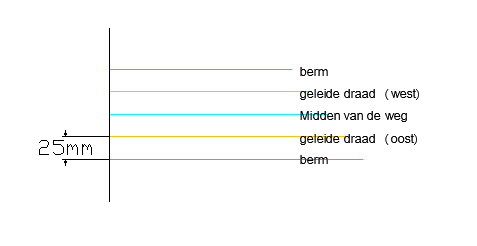
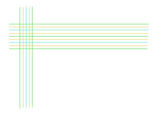
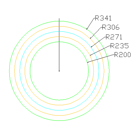
In this picture you can see the colour codings I use:
- Green is the outer limit of the road where the grass or curb starts. You may want to add a bicycle lane here.
- Yellow is the guide wire.
- Blue is the centerline of the road where the dividing line will be painted.
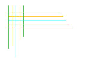
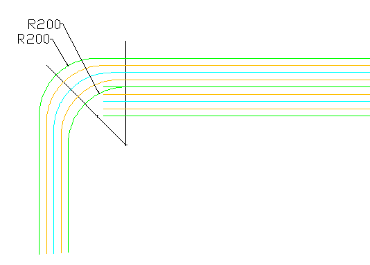
Let’s start with a basic two-lane corner. I use a CAD package to draw the road but you don’t need to with this method. You can do it directly on your table or a sheet of paper. You will need to draw only one radius so all you need is a piece of cardboard.
Corners
A car on the outer lane will tend to run over the middle of the road. To compensate for this use the same radius for the inner as well as the outer guide wire. Use the same radius for the sides of the road.
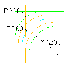
remove the extra lines and redraw the needed lines to clean things up.
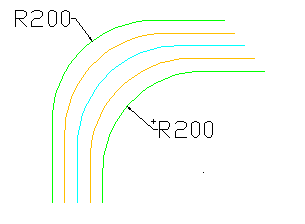
Now you can see the effect of repeating the same radius over and over again. The road in the corner is much wider than a straight road.
If two roads intersect at a sharp angle then this method has a unrealistic side effect.
The 200 millimeter radius creates a very large corner area.
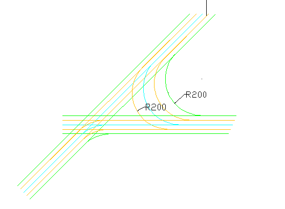
In our model world we can avoid this by not installing a guide wire in the acute corner. Just draw something that looks realistic.
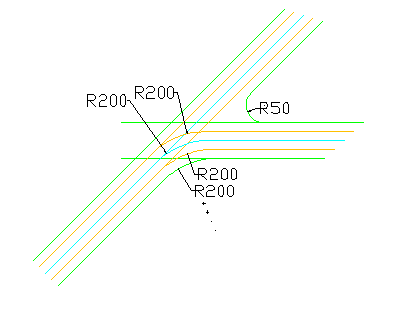
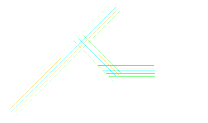
This same problem must be solved in the real world. It may be done by adding a perpendicular piece of road to eleminate the sharp corner.
Now draw all the 200mm radius curves.
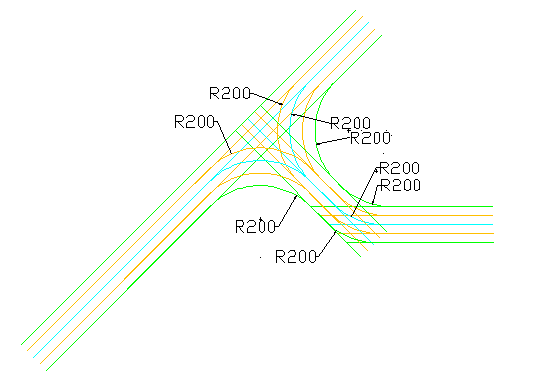
Clean up the extra lines.
The circles are where switches are needed.
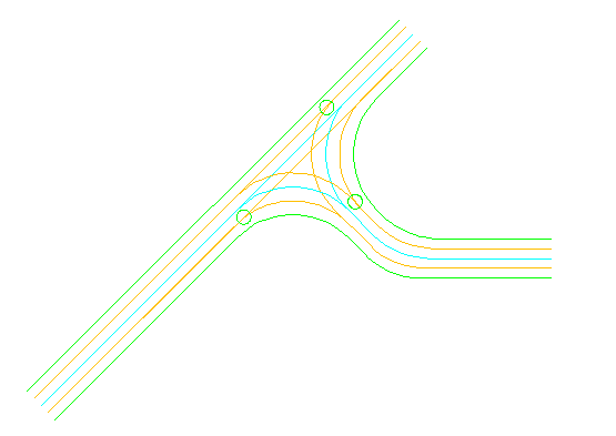
Three switches are needed for a two-lane corner compared to the first example which needed only one.
Loops
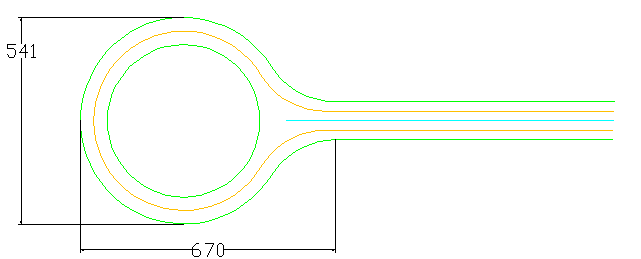
A single loop can be constructed as follows.
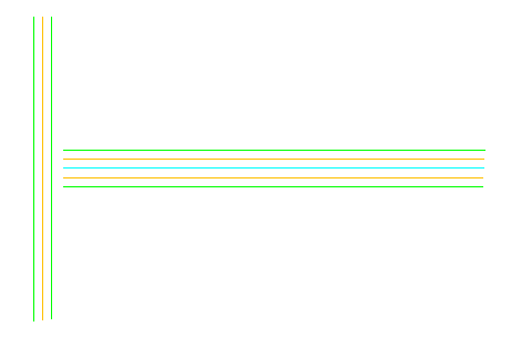
Start with the basic road dimensions, two lanes and a single lane
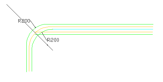
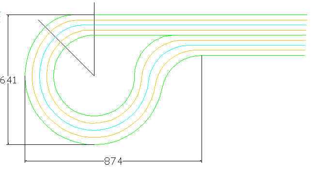
Then construct a single corner. Draw a line at the widest point of the lane, this will be at a 45 degrees angle.
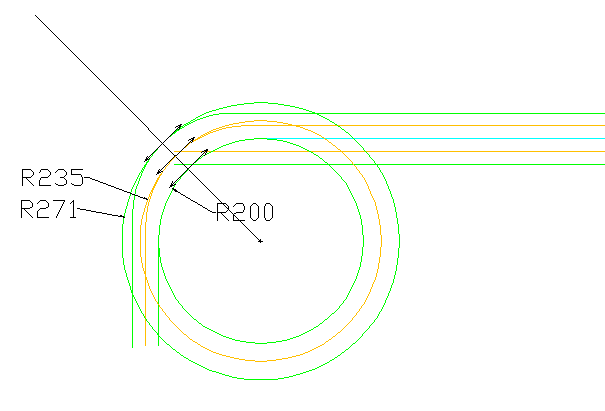
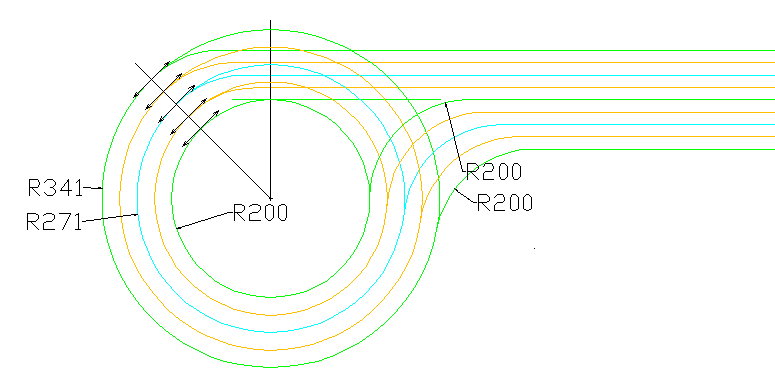
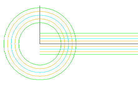
Now in this next step you extend the widest point in the corner into a concentric set of circles. Three radii: 200, 271 and 235 mm.
For this you will need a compass. Set one leg in the centre of your 200 mm radius card board, the other on the 45 degree intersection and make a circle.
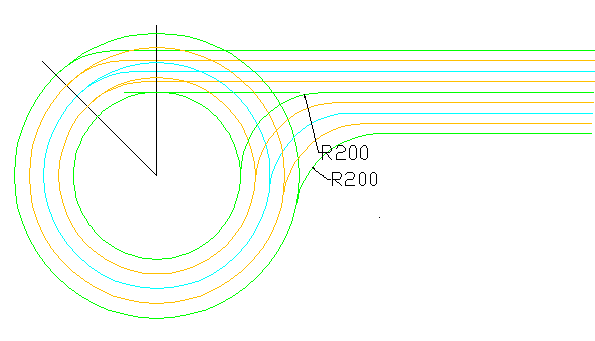
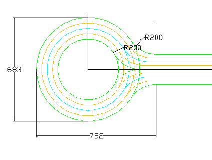
Fill the connection to the second lane, again using the standard minimum 200 mm radius.
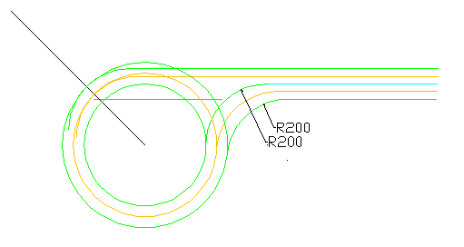
Clean up the extra lines and there you have a single return loop.
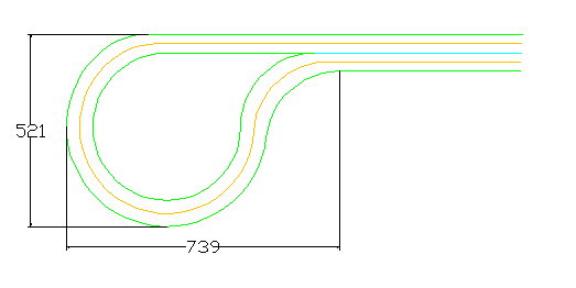
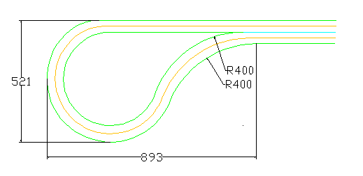
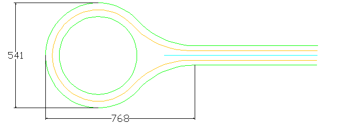
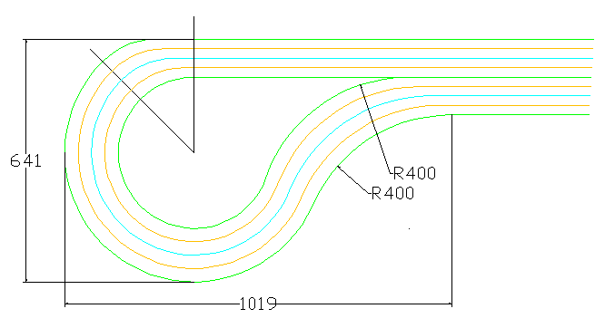
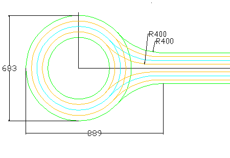
I prefer to use 400 mm for the returning fillet. This just looks better and does not take to much extra space.
Centre lane loop
Another variation is a return with the loop in the centre of the two lanes.
For this you reuse the concentric set of circles from the previous example (Three radii: 200, 271 and 235 mm) and fill the corners with the standard 200 mm radius.
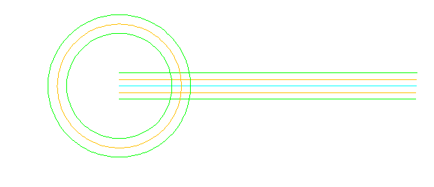
…or use the 400 mm radius, takes just a little bit more space and looks much better.
double loop
Double lane centre loop
Another way to construct the loop is to have the circle in the middle of the four lane road. For this we reuse the concentric set of circles as drawn before with your compasses.
now extend the centre of the circle and offset the lanes with 25 mm.
What about the signal wire?
It may be a bit confusing but remember these three basic rules:
- Different directions are needed on each side of a guide wire.
- When two signal wires are very close to each other, run them in the same direction.
- Try three times and you will find a way to do it.
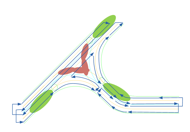
There are three sections shown in green where the signal should be optimal. This is also where cars need to stop.
The red zones will not have good reception but the cars simply pass through and do not need to receive commands.
You see, it’s possible. And if you wonder, yes it took me two attempts to get it right 🙂
Now finish the road by painting it (not according to Dutch regulations)
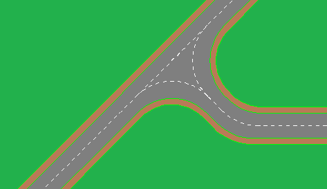 Looks realistic enough to me…
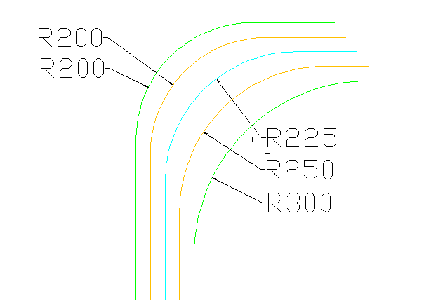
Not-so-average
The construction drawings as described are based on a practical use with average cars. Always test it with two cars before finishing your surfaces.
Long trailers may even need a wider inner corner. Try the following radii and retest with your vehicles.
Hans Nouwens.
With English text corrections by Mike Morey. Mike volunteered to prioritize his busy project planning and make room for helping me with my very Dutch English. Thank you Mike!