Tag archieven: detectie

Connecting MCC detection

Ok, the documentation is there. It’s available in English too. I still get questions about connecting the reed switches. The diode matrix I made for my test track was a quick hack with available materials. After evaluation this design was not very suited for a publication. This is a second attempt to design a cheaper alternative for connecting the reed switches.

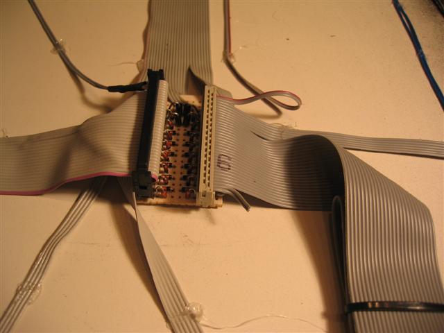
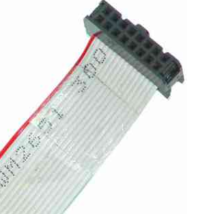
About the UCCI. The black multi pin connectors you may recognize as a floppy or hard disk cable connector are used on the UCCI to connect the reed switches. You cannot connect the switches directly to the controler. They are multiplexed. Now for some of us this is a somewhat mysterious technique. I will not try to explain this, just google for the numerous explanations. Just think of it as a way to connect lots of reed switches with as little cables as possible.

ucci2_large


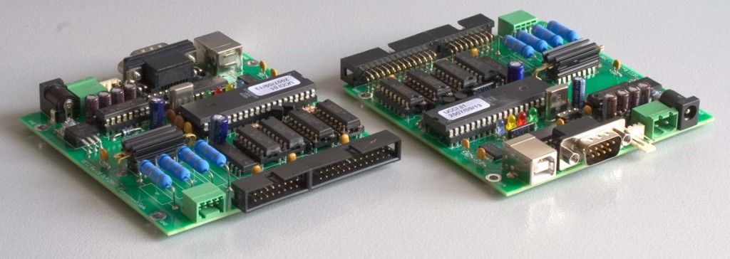
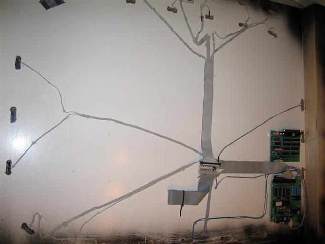
Leon kindly designed a diode matrix for us. You can order it from his website.  Before this was available I designed a prototype for Railz Miniworld. Combined with the test track thingy I now present a do-it-yourself version of the SWDEC.

swdec_small

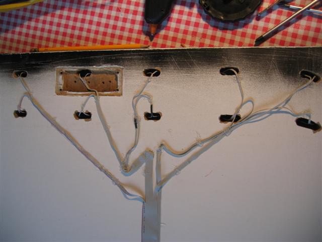
With two flat cables you can connect 128 reed switches. It does not matter which connector you use first. The flat cables can me about 10 meters each.

It is advised to use them as described in the next picture:

16-26pin connector


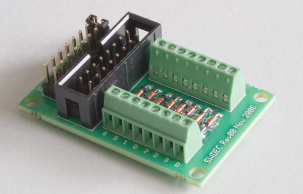
All the connectors are female connectors.

16pins-female


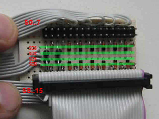
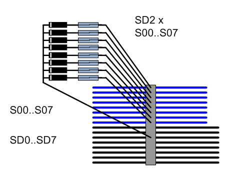
The reed switches and diodes must be connected as shown in the next picture. Each reed switch is connected to a single Sxx channel. the return connection is one of the SDx channels.

For every connector you will have to choose a different SD channel.


connecting reed and diodes

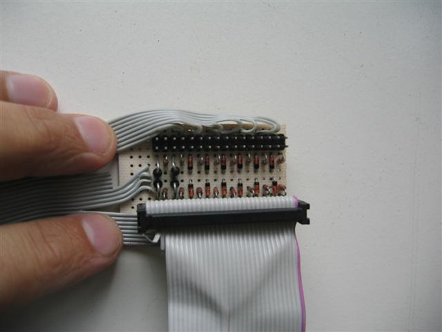
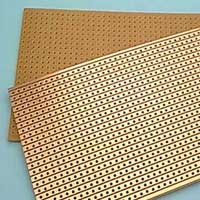
The board to use is called strip board or Veroboard.

stripboard


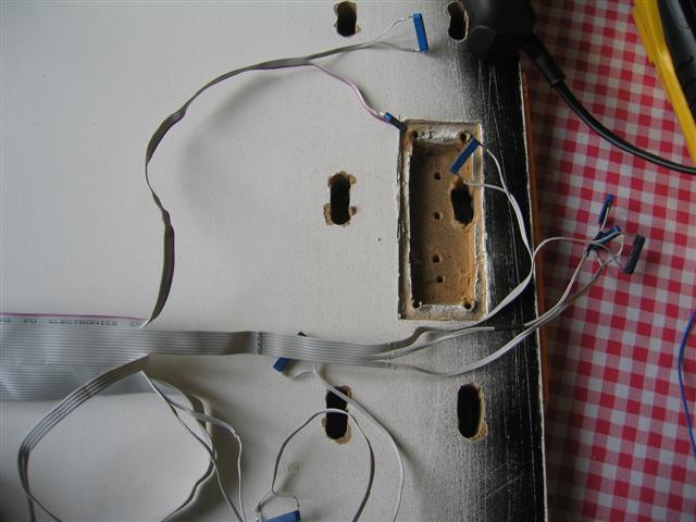
First the back side. In the middle you will have to remove three stripes of copper. On the corners you will need some holes. Remove the copper around the hole to prevent a short circuit here.

The grey line is a extra connection you will have to solder on the copper. It connects the 8 bottom stripes.

selfmade flat cable matrix

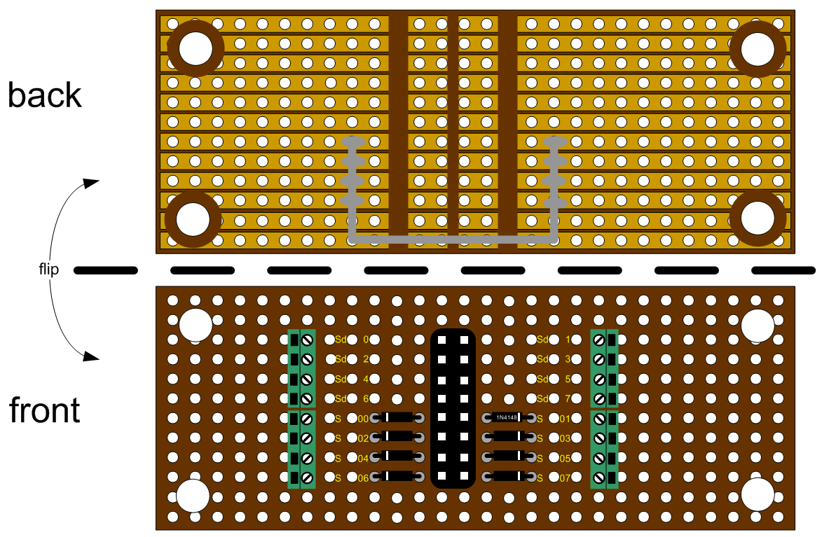
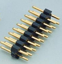
On the front side you place the connector. This is a print header. Buy these in long strips and break or cut off 16 pins.

header
Eight diodes of the type 1N414B. These are the cheapest you can find. The indicator ring is on the outside pointing away from the middle 16 pin connector.

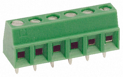
The green connectors are very expensive.

R101538-01

Of course you can decide to skip these and solder your wires directly to the copper on the back.

The green connection is unique for every matrix you make. It chooses the return channel. In the example SD2 is chosen. If you look at the back you can see that this connection touches the wire on the back side indicated with grey in the first picture.

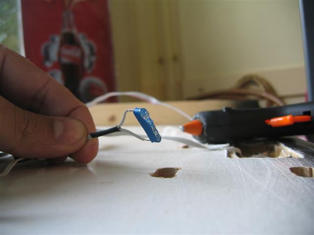
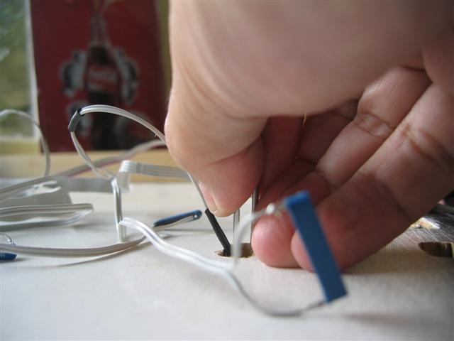
The reed switches are connected as shown. One leg on the SDx channel, the other via the diode to the Sxx channels.

connecting matrix

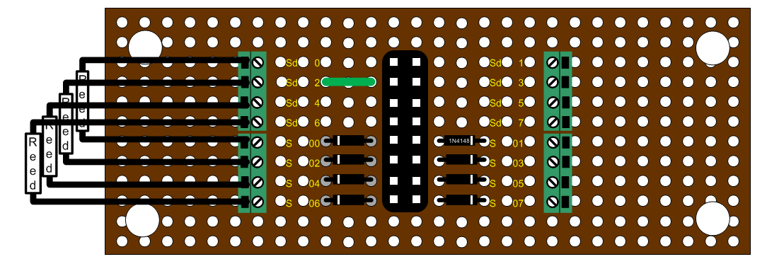
That’s it. Don’t forget to change the green connection for every board you make. On every flat cable you can connect 8 of these boards.

Good luck!

Please send me some pictures of your results.

Hans.

Testbaan – detectie

De auto’s kunnen nu hun rondjes maken maar kunnen nog niet aangestuurd worden. Onder de baan moeten de volgende zaken gemonteerd en aangesloten worden:

  • een reed-contact per blok
  • diodematrix
  • de UCCI
  • Een OM32

De UCCI heeft wat ruimte nodig. De vermogensweerstanden en de driver er voor (met de zwarte koelribben) geven behoorlijk wat warmte af. Leon raad aan een afstand van 1 cm aan te houden. De OM32 kan direct op de plank.

De voeding haal ik uit een adaptor. De groene stekker gebruik ik om deze voeding door te voeren naar de OM32. Op deze testbaan zal ik niet veel vermogen verbruiken. Kijk in de UCCI handleiding voor de aanbevelingen.

De blauwe draden zijn de zenddraden die langs de wegen liggen. Een enkel paar in mijn geval.

Via een lintkabel sluit ik de reed-contacten aan. Ik had niet de juiste stekkers in huis dus ik probeer het af te maken met de (gratis) dingen die ik nog had liggen. De lintkabel is een kabel die in een PC wordt gebruikt voor een floppy drive. Daar heb ik er nog wel een paar van op de zolder.

Na de diodematrix gebruik ik weer zo’n kabel, het blijkt een lekker overzichtelijke methode te zijn. Niet te veel losse draden. Aan de uiteinden zitten de reed-contacten.

Op de OM32 zit een klein testprintje met een zestal leds. Dit is tijdelijk.

Een detailfoto van de ter plekke verzonnen diodematrix. Leon biedt een matrix aan met acht aansluitingen, ik had er minstens 24 nodig.

227_2709

Op ieder setje pennen kan je een reed aansluiten. via een diode komen ze om de beurt bij de SD kabels 0..3. De SD kabels 4..7 gebruik ik niet.
Die vier grote diodes hebben geen speciale betekenis. De kleintjes waren gewoon op.

Vooraf heb ik geen moeite gedaan om uit te rekenen welke nummers de detectors zouden krijgen. Het maakt in de software namelijk toch niets uit.
Bedenk wel dat de nummers die dinamo geeft door koploper met 1 opgehoogd worden.

227_2710


Hier liggen de reeds in de buurt van de gaten onder de geleide draad. Het rechthoekige gat heeft geen functie. Hier zat vroeger een handvat in, de plaat was vroeger een deurtje.

227_2711

Een reed aangesoldeerd.

227_2712

Met hete lijm

227_2713

En dan tegen de geleide draad aanplakken.

227_2714

Al snel zitten de schakelaars vast. Op deze manier is het een makkie. Bij Railz heeft een medewerker zo 500 contacten achteraf onder de tafel aangebracht op zijn rug. Op de testbaan was het in tien minuten gedaan.

227_2715

De lintkabels gaan ook met hete lijm vast aan de tafel. Ik heb nog een paar aansluitingen over.

227_2716

De hergebruikte stekkers hebben twee gaatjes te veel.

227_2717

Al met al een relatief snelle manier van aansluiten, minimale kosten en het werkt!

Hans.